
Monthly Mechanism: Differential Screws
Monthly MechanismDifferential ScrewWhat happens if you put a screw inside a screw?
Today we're kicking off a regular series on interesting mechanisms, starting with the differential screw; a very compact mechanism for generating very fine motions. Their small size makes them a bit hard to spot in-the-wild, but these are commonly seen in precise positioners, able to scale finger-knob rotations down to nanometer displacements. For instance, ThorLab's nanoMax stages uses 3 differential screws to drive a kinematic stage with nanometer precision.
Differential screws are mechanically simple and very compact for their mechanical advantage, consisting of three parts related through two threads. They are usually seen in two primary configurations:
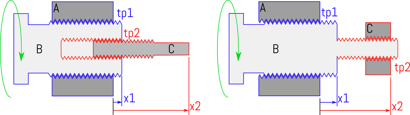
In the left configuration, the internally threaded part A is assumed fixed, dual-threaded part B is rotated by some user, while externally-threaded part C is free to translate while prevented from rotation. The right configuration merely gives C the internal thread and B two external threads; other permutations are possible but often more challenging to produce. Parts A and B interface through thread pitch 1 (tp1), and B and C through thread pitch 2 (tp2).
Calculating travel
Converting threads per inch into length per radian, , rotating B causes it to translate with
.
As C can only translate, B's rotation also causes a displacement between B and C of
.
Rearranging we find
.
This is rather hum-drum; where it gets more interesting is in the choice of the thread pitches. The 'differential' screw refers to the common case where tp1 and tp2 differ in their handedness, say tp1 = 24 threads per inch right-handed, and tp2 = 28 threads per inch left-handed. Representing right handed threading as positive and left as negative, converting units
and
.
Giving , which for a full turn , all with two common threads.
Physically, we would see that turning B to the right (positive) causes it to translate to the right, while the left-handed threads on C would cause it to screw into B. If instead we had made tp2 right-handed and tp1 left, this would have produced a negative effective pitch, causing B to translate left and C to emerge from B. As it is only the thread difference that matters, it is trivial to make a table of common thread pitches and resulting, effective pitch:
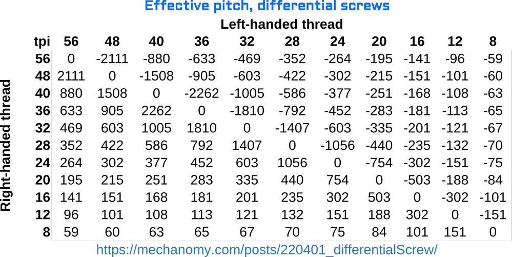
On the diagonal, right and left threads of the same pitch produce null motion: between endstops C will not move. Not shown is that differing threads of the same handedness will cause their 'addition', making C move faster than B.
In use
The long engaged length and typically fine thread pitch prefer lower viscosity lubricants than would be expected for a leadscrew. Backlash is less of a concern given the fine pitch, lubricant, and tens of engaged turns, but it still shows up directly on the output, as do any thread errors. The main design challenge is ensuring the guidance of the moving parts, that the coaxial alignment is maintained throughout the range without impinging the thread.
Comments? Find Mechanomy on Twitter, and send us suggestions for future monthly mechanisms!
— Ben Conrad
- Next: Following Mechanomy
- Previous: Modeling Ideas