
Text to CAD?
substackAILLMdesignengineeringZoo is an interesting startup building, essentially, a SAAS API for mechanical CAD operations, or as their website says "Zoo creates infrastructure for hardware design". In this post I'd like to talk through their text-to-CAD product which leverages that SAAS backend, and what this approach to design tooling means for hardware engineers.
What is Zoo's text-to-CAD application?
If I ask you to buy a 24 tooth spur gear, could you do it?
That depends on our shared context; you could buy some random gear by assuming the information that I didn't provide to you, or you could look at the project files and design analysis and select a sufficient gear for the project.
Asking Zoo's text-to-CAD application for a 24 tooth spur gear,
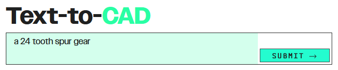
yields STEP, glTF, and other formats of a 3D model:
Some quick takes:
- this is a really cool capability shipped quickly by a small team.
- the gear model is basically what I requested, having 24 teeth of apparently involute profile.
I was not asked for the design context or to supply some of the missing parameters, it just replied with a gear model, caveat emptor. (It should be said that it is not easy to communicate design context, intent, and risks within a team, so at the very least we should limit our expectations.)
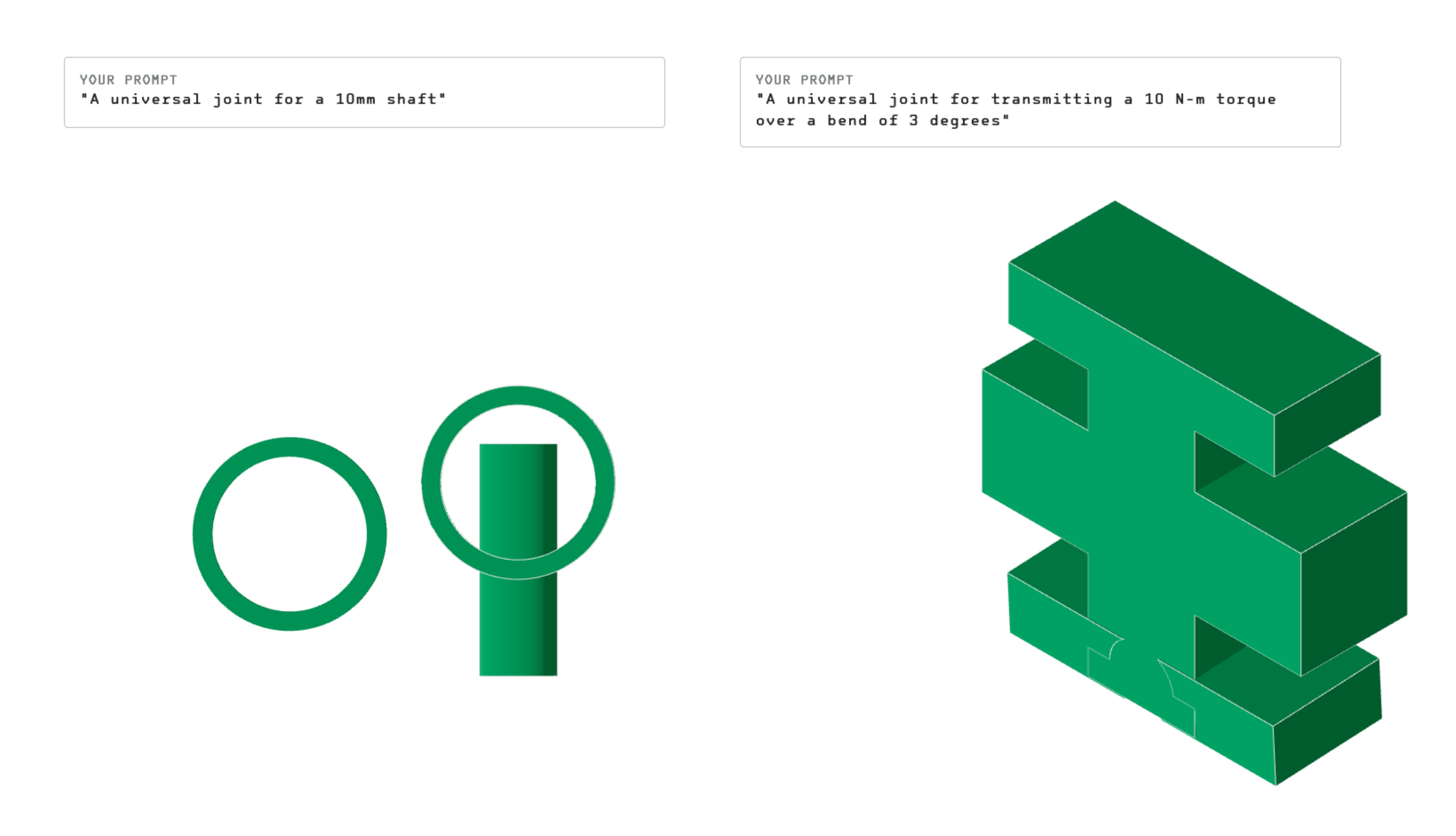
It can also fail:
So, what did text-to-CAD assume about gears, how did it generate the model, and is this a step towards the tools of tomorrow?
Is the model correct?
First, there are 24 teeth. The outer diameter measures 26mm with a 10mm bore and 10mm thickness. Comparing the Zoo model to this gear from SDP-SI, they are virtually identical.
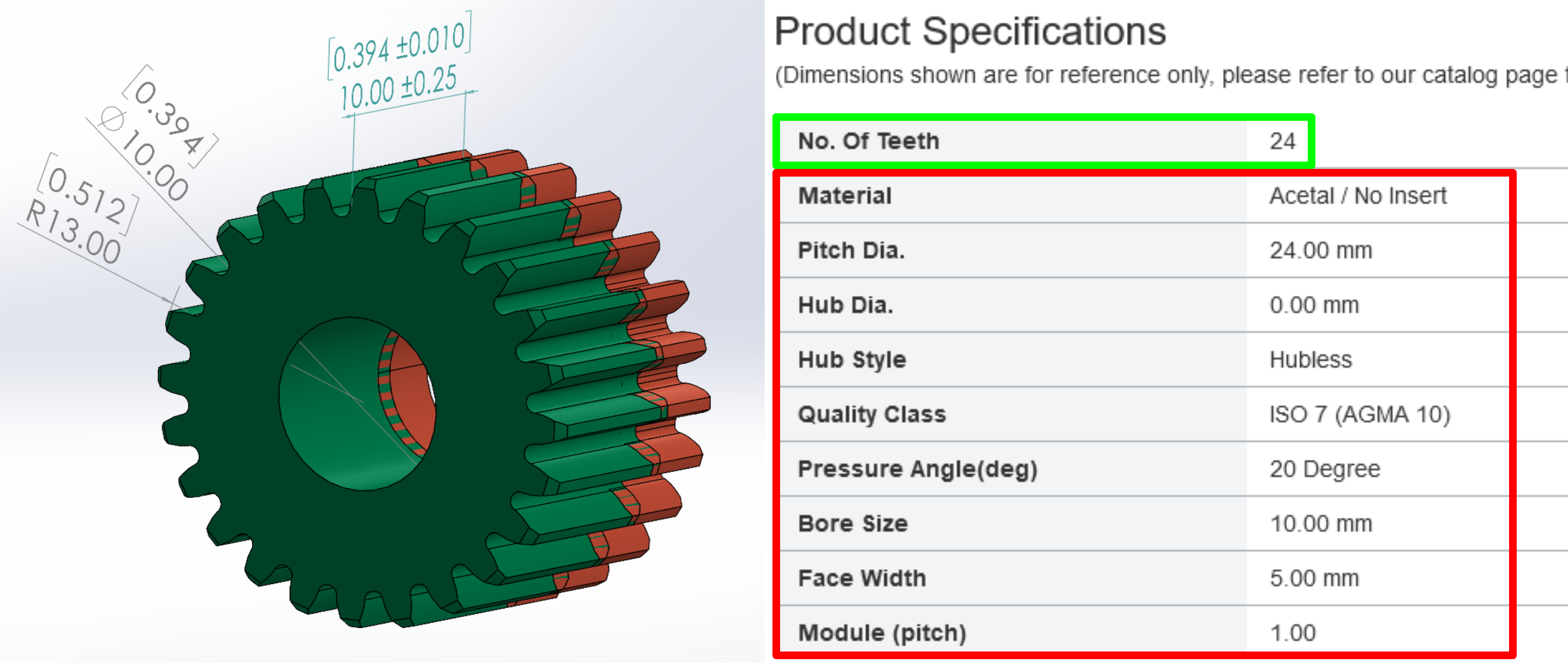
Without any association to a physical gear, the generated model is only useful for virtual prototyping and 3D printing; purchasing would require specifying the additional details of material, availability, and pricing, in which case it would be better to use the supplier's model.
How does it work?
To start, I don't know and Zoo has not discussed it in sufficient detail; the current alpha is likely a few-shot approach to a large language model (LLM), where some examples of parts in the KittyCAD Modeling Language are added to your prompt, but this section is necessarily speculative and general.
This few-shot approach might look like:
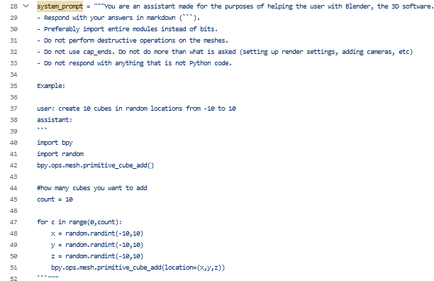
or
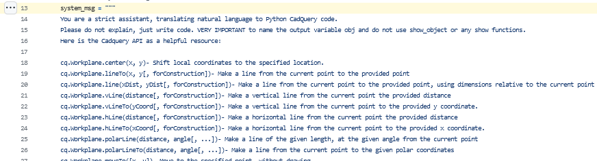
In both cases, the design is to tell the LLM some basic information about the general task and operations to prepare it to receive and respond correctly to the user's input.
Returning to Zoo, the introductory blog post explains the difference here from other efforts:
There are lots of text-to-3d models that exist for gaming asset use cases but there are no Text-to-CAD models. The distinction being that we do not use point clouds, we generate B-Rep surfaces. So you can import a STEP file from Text-to-CAD into any existing CAD program and edit it. The existing text-to-3d models generate meshes so if you were to import that into an existing CAD program, it would just be one large amorphous blob and not editable in any useful way.
The focus on a boundary representation of surfaces (B-Reps) is a key differentiator from merely 3D point-based approaches. B-reps are actual equations that collectively describe surfaces and edges of a model, while the latter point/mesh approaches assume a spatial grid, with AI solving 'what color will make this pixel/voxel more likely to be described like the given text?' on each. This representation distinction is also why every CAD user has been frustrated with trying to work with point cloud data, say from a 3D scanner: 3D points lack the clean precision of objects created by math in the CAD kernel.
Continuing,
Generating CAD models is a lot different than generating images or video. Models generating 2D images, 2D video, and 3D point clouds are learning from datasets with dense, highly descriptive and strict representations of data that each have one and only one representation. In contrast, there are multiple valid feature trees for each CAD model, so training and validation are not straightforward.
Whereas an image is represented only by its matrix of pixel colors, the design concept embedded within a CAD model is encoded across several layers of intermediate representation via sketches and features which combine to form a 3D model of the concept. To take the example of a hole for a fastener, a series of extruded cuts or a single revolute cut can both produce the same 3D hole, but these are parameterized differently. These intermediate layers of representation allow complex features to be designed in multiple ways, providing flexibility but frustrating attempts to learn a single way to create a particular feature. In natural language, this would be like having words that are synonyms only in the context of certain subjects, a tedious and sometimes confusing state.
A few more details on the approach are given on their machine-learning api page, though it is not necessarily the case that these capabilities are active in the text-to-CAD application:
Starting with our Text-to-CAD endpoint, anyone can build prompt interfaces to generate starter CAD models. The machine learning behind ML-elephant is trained on our proprietary data sets, and uses our Design API to programmatically generate novel CAD files.
The infrastructure behind Text-to-CAD utilizes our Design API and Machine Learning API to programmatically analyze training data and generate CAD files.
By fine-tuning our machine learning models on your data, you can rapidly leverage your existing data to create specialized Text-to-CAD generators without building and maintaining infrastructure.
The overall architecture appears to be:

Starting in the upper left, the textbox input ("a 24 tooth spur gear") is fed into the LLM which produces a parametric description in the KittyCAD modeling language of the requested object, if within the database's training. This part description is processed by the modeling kernel into a 3D boundary representation which can then be rendered as 3D surfaces that are displayed in the text-to-CAD model viewer and downloaded by the user.
All of the parts in the diagram are required, but the novelty is due to the part database and the LLM trained on the database, and this is the part that they have not discussed publicly.
On learning CAD
In AI product development I said that:
...the advances in image generation are entirely the result of having large image databases of a wide variety of regular scenes with generally accurate and specific labels that describe the scene. In contrast to photo services like Getty, which hosts many professional photos with strong and unambiguous labels, sites like Thingiverse have many fewer 3D models and presently lack descriptions of form and function. Indeed, today's 3D platforms have an altogether different business model than the stock art services, focused on assets for 3D rendering and printing, and both of these are much smaller uses than the every-article-must-have-a-title-photo practice of digital publishing that tied stock art to the rise of online news and commentary. Lacking this database, you cannot train an AI to link feature descriptions to the 3D data that provides that feature.
I still think that a database of objects and descriptions is necessary for any AI tool actually be useful, but one of the advances in text LLMs is their ability to learn from their own predictions and self-correct,
Many early machine learning algorithms required training examples to be hand-labeled by human beings. For example, training data might have been photos of dogs or cats with a human-supplied label ("dog" or "cat") for each photo. The need for humans to label data made it difficult and expensive to create large enough data sets to train powerful models.
A key innovation of LLMs is that they don’t need explicitly labeled data. Instead, they learn by trying to predict the next word in ordinary passages of text. Almost any written material—from Wikipedia pages to news articles to computer code—is suitable for training these models.
For example, an LLM might be given the input "I like my coffee with cream and" and be supposed to predict "sugar" as the next word. A newly-initialized language model will be really bad at this because each of its weight parameters—175 billion of them in the most powerful version of GPT-3—will start off as an essentially random number.
But as the model sees many more examples—hundreds of billions of words—those weights are gradually adjusted to make better and better predictions.
The expectation is that, with a sufficiently large database, the LLM can learn the steps to create a model, reading between the lines to judge not just the final output but also that the steps in reaching that output are consistent with the good practice seen in the training set. Some of the ingredients for this database can be seen in McMaster-Carr's product catalog: of their 700,000 industrial products, 380,000 fasteners and machine parts have CAD-native 3D models:
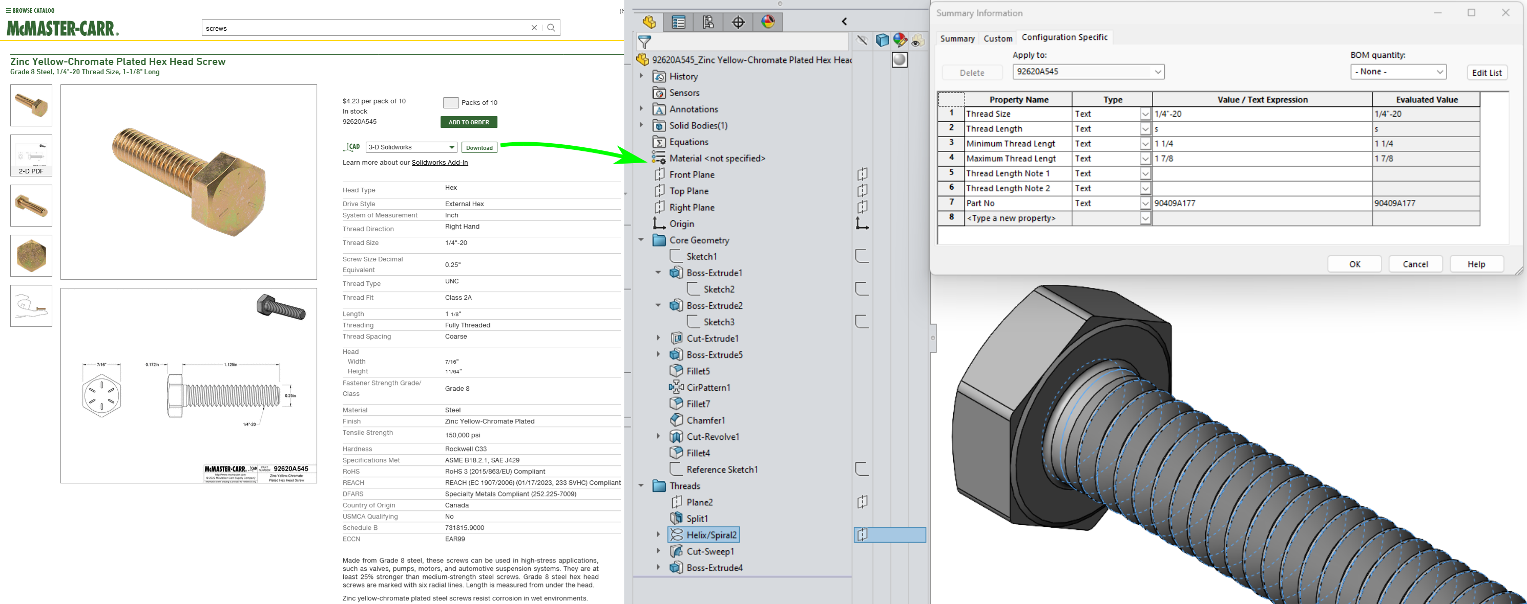
Downloading the Solidworks file, I can see all of the modeling operations that were performed to model this particular bolt. To change the bolt I need only to locate and edit the appropriate parameter. With thousands of slightly-differing bolts in their catalog, I should be able to learn what few numbers change between each and the connection between the product description, the sketches and features, and the resulting 3D model. But in studying the bolt models, I can also learn a modeling strategy of: start with the head, then make a cylinder, then put threads on the cylinder.
This modeling strategy is opinionated and does not identically apply to modeling other parts, like nuts or washers, but within the class of bolts following it should result in a correct bolt. The challenge of generative CAD is in generalizing beyond the training, of getting outside of the database of trained models and doing something new. This has been labeled
The creativity gap: In conventional [deep generative model] applications, the overarching goal is to mimic the training data and emulate existing designs. In engineering design, emulation of existing products is often undesirable. Designers typically aim to introduce products with novel features to target new market segments.
As most designers will attest, the creative act in modeling is in taking a mental concept and breaking that into primitive sketches and features that collectively realize that concept in a 3D model. We don't talk about this act, nor do our tools elicit this from us, we just do it and make a model. I argue that some of the key information in CAD modeling is not present in the existing databases, even when you have full access to the feature tree, and I am not yet persuaded that AI learning is as unbounded as human learning in this domain.
I would also argue that CAD 'languages' differ significantly from natural language, both in quantity of data to learn on and in the quality of the representation. In natural language we generally create conceptual precision by adding words: the quick brown fox is a fox, that happens to be brown and is also quick in its movements. Changing the adjectives changes the meaning, but increasing the precision of the adjectives, saying "#964B00" instead of brown, hasn't added useful meaning but erroneously constrained it. Our parametric CAD paradigm is rooted in real numbers, not additive grammar, and no amount of tweaking the color code or moving a point on a sketch will remedy this representational error.
While I can verbalize sketching
relative to the origin define a line making an angle of 45 degrees between a point on the X axis and a new point 300 mm from the origin
I'm not actually using language to describe design concepts. Describing a sketch relationally
create a six-sided polygon such that two opposing side are vertical in order to register on the fixed and moving vise jaw, another side is horizontal to provide locate the part vertically, with the remaining two sides vertically-symmetric about the center and making equal angles with their adjacent sides so as to center a cylindrical work piece placed between these two sides (describing a V-block)
is better but may quickly run into a challenge similar to that of defining what art or beauty is, of trying to correctly and exactly describe one version of a feature over another. This challenge is not uniquely found in GUI-based parametric CAD, as code-based modeling applications also rely on visual reasoning and mental tracking of the model state, arguably because both code and language lack the grammar to state intermediate concepts correctly. Already this is seen in the challenge of prompt writing, where the inability to uniquely describe the desired output results in a lengthy, textual search of the LLM for something approximating the imagined concept.
So, I don't think that it is or will be easy to construct or train on a CAD dataset, or that you can get away with a small number of models and reason out to general capability, at least under the present approaches in CAD and AI.
Towards the tools of tomorrow
Stepping back, does the correctness of the generated gear matter? Or what level of detail is required for a gear or any model to be 'correct', and when does this correctness matter? Already McMaster-Carr and other distributors disclaim the accuracy of their CAD models,
The 3-D CAD models and related information are provided for reference only. The CAD models do not contain any technical information other than what is readily observable, specified by industry standards or provided to us by our suppliers...The dimensions and other technical specifications of our products may vary from those shown in the CAD models...
To give an example, if I have 5 gears laid out in a line, my intent of forming a gear train is reasonably clear even if my gear selection is deficient. What the mechanism designer cares about is whether the gear transmission can transmit the power desired, and that its components are selected according to some metrics like availability, transmission efficiency, mean time between failure, factor of safety, backlash, inertia, etc. But not all of these can be determined a-priori when selecting a gear. Some, like backlash and inertia, require analyzing the entire transmission and often physical prototyping and testing. Others, related to purchasing, are frankly better chosen by a dedicated purchaser who is aware of the manufacturing schedule, than the original designer months ahead of production.
Right now we use standards to fix the engineering aspects of a design while leaving the sourcing and purchasing details for later: buy something meeting this specification and the product should work. But as manufacturing becomes more programmable and supply chains continue to be scrutinized, there will be increasing pressure to defer some of the engineering details for market or other business reasons.
Just as the best systems are robust to widely changing inputs and external disturbances, remaining performant and useful until they fail in a predictable and proportional manner, so too should robustness of the system design be valued -- design meaning the total collection of the engineering formulas, analyses, test results, architecture, subsystem divisions, material selections, interface technologies, tolerancing rationales, and all other choices made while designing the system. I would argue that we are stepping toward a more hierarchical and iterative approach to systems design, where general goals are stated and their implications rendered, evaluated, and used to organize the next level of detailed design work.
At the end of the day, I want to be able to optimize the overall system design for any variety of purposes, some of which, like market response, I cannot know during design but will dearly desire once the production clock starts ticking. In order to do this we need tools that allow specification of only the essential aspects of the design; the less I specify, the less the design will be constrained in some later stage. Imagining, then, a more general AI-powered design assistant, I would like to just request "a gear transmission transmitting 3N-mm of torque between shafts 83mm apart with a 2:1 transmission ratio" and receive something that looks like that, something that I can include in the design that is correct enough to be able to get onto the next subsystem. Then, having coarsely described the system end-to-end, my team and I can dive into modeling each subsystem to ensure their correctness, consistency, and performance within the context of the overall system design.
Text-to-CAD allows some simple parts at one level of a system to be specified briefly and textually, making very clear what the designer is and isn't intending to specify, if the prompt is maintained along with the model. This tool presently lacks a place in an overall design workflow, but it is a step in the right direction.
I hope designers and engineers are paying attention to these developments, not because they are ready or even capable of professional use, but because now is the time to push these capabilities in directions that actually improve productivity and design quality and away from marketing hype.
— Ben Conrad
- Next: Value Loops
- Previous: Mechanomy's Fifth Birthday