Moover
We hope you appreciate this overview of our Moover project, our first in-house demonstrator of some of the ideas and capabilities of our pre-CAD hardware design tools. This work produced 7 conceptual prototypes, kinematic design tools and dynamic performance analyses, and one provisional US patent application. This page is not a tutorial of our tools, but rather an overview of a reference system that provides a context for discussing our tools and design approach.
All of the design decisions made in the following variants were made through our modeling libraries, particularly the BeltTransmission library. Their feature sets will expand with continued development and use, but even now they provide the ability to determine key properties of a potential belt transmission before starting CAD design.

We are looking for partners for further development, say hi if you are interested. The remainder of this page gives a quick tour of the Moover architecture variants and some of the ideas and key conclusions from each.
Motivation
The Moover project developed several variations on the design of a differential belt transmission for application in linear stages (positioners). In these machines, the industry-standard design consists of a fixed motor with drive pulley and a freely-rotating return pulley, separated by some distance. Between these a carriage moves along linear guides, according to the motion of a belt stretched between the driving and return pulleys.
Static or dynamic loads applied to the carriage are borne by the linear guide in directions transverse to the direction of motion, with the cable or belt transmitting loadings along the direction of motion to the fixed torque source.
Transmissions are commonly interposed between the motor and the carriage to reduce the required performance of the motor, often trading rotational and translational speeds for increased torque and force, respectively. The majority of these transmissions take the form of a gear reduction between the torque source and driving pulley. In the Moover variants, this transmission is a differential belt transmission which employs a clever arrangement of one or more belts and various pulleys to create large reduction ratios without gearing.
Kinematics
As described in our differential belt monthly model, at the core of the differential pulley transmission is the requirement that the same belt or cable engage two coupled pulleys. Where previously the carriage moved exactly with the belt, the coupled pulleys introduce a transmission that enables the carriage to move at a fraction of the belt speed.
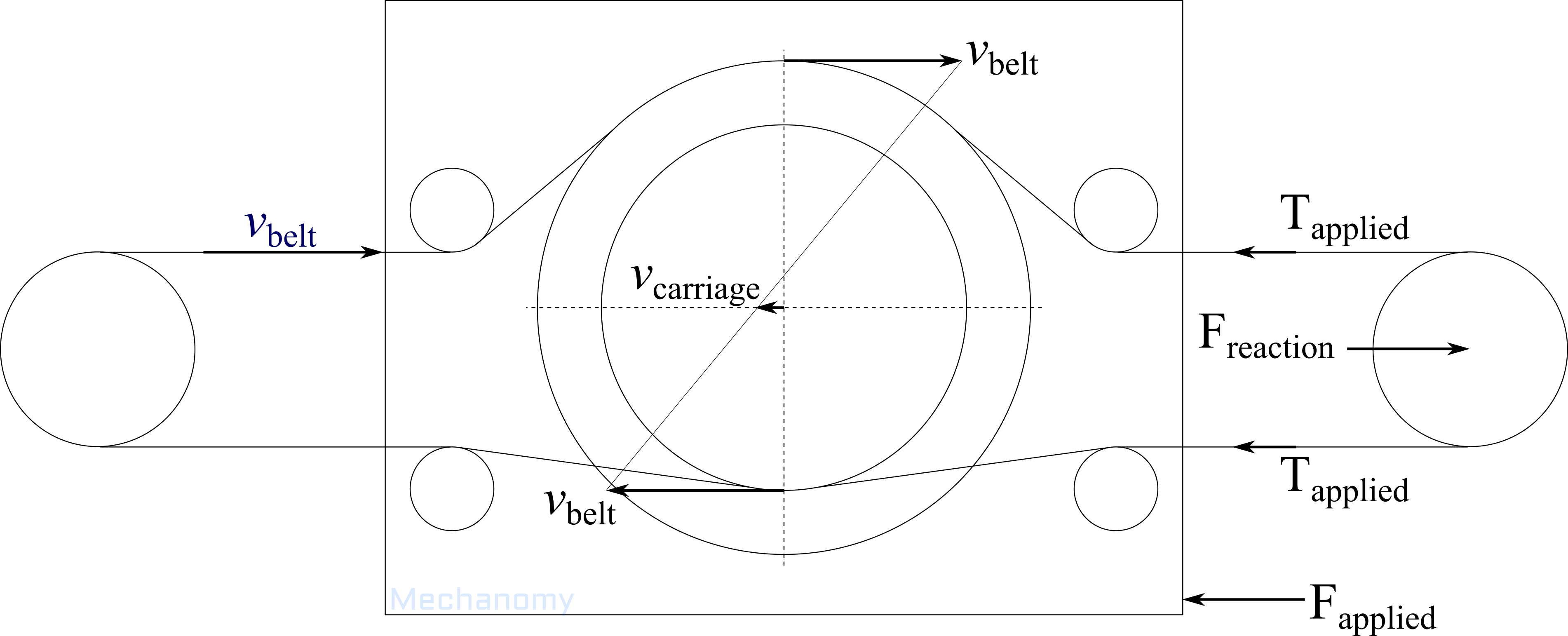
In the simplified system diagram, the drive and return pulleys are fixed in space while the carriage assembly translates horizontally. The single, continuous belt engages larger and smaller coupled pulleys, giving each the same tangential velocity. As the pulley radii differ, these identical tangential velocities are resolved through motion of the carriage, as depicted.
The transmission ratio is determined by the difference in the coupled pulley radii
which can be used to find the carriage velocity
and position
The leading negative sign in the transmission ratio indicates that the carriage moves oppositely to the belt segment engaged with the larger pulley. Of course, when used with toothed timing belts the transmission ratio is limited to pulleys having integer numbers of grooves.
Variants in the prior art
DualSingle variant
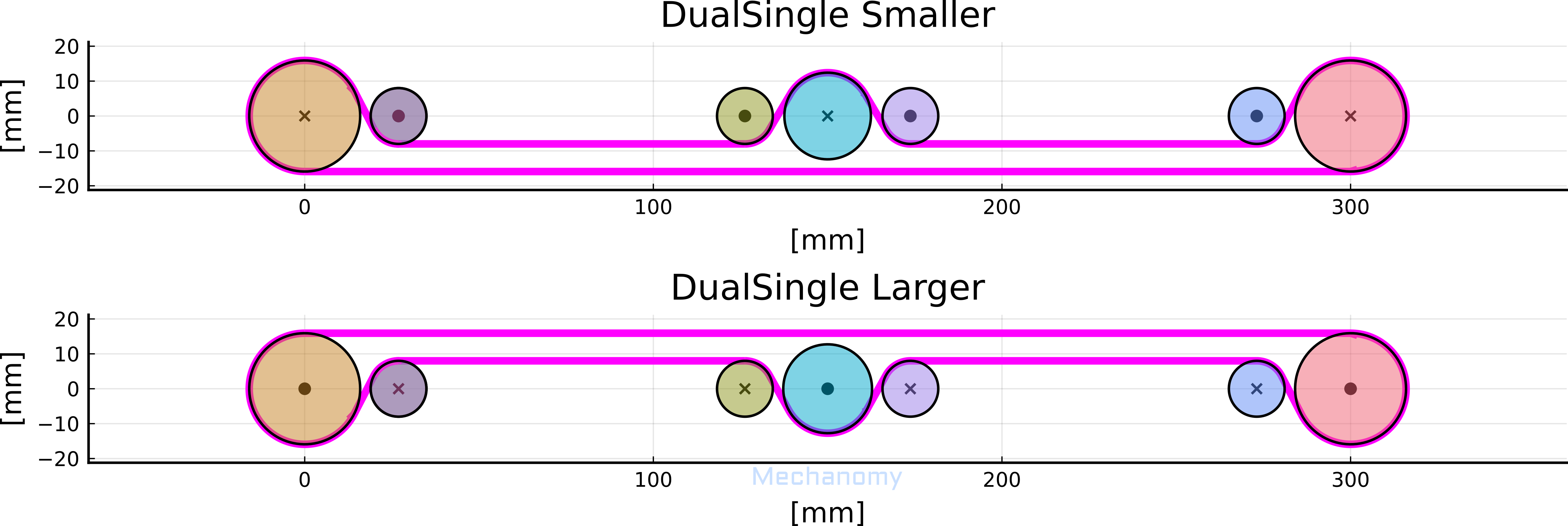
Since the smaller and larger coupled pulleys are coaxial, planar belt and cable routings are challenged to engage both pulleys. This has been solved previously by using two belts or cables, one for each coupled pulley. The first prototype variant recreated this concept in the form-factor of a small linear actuator, named DualSingle for the dual, parallel belts and single driving motor.

The open carriage and return assemblies showcase the typical dual-belt routing. The drive-side, carriage, and return-side idlers are positioned to such that the belt segments between the drive and carriage, and carriage and return are straight, which ensures that the belt length is constant as the carriage translates.
39 and 40 groove pulleys on the carriage create a transmission ratio of -0.013, allowing an ancient stepper to animate this variant. This dual-belt differential can be made more compact by locating the drive, idle, and return pulleys on the same shafts. This routing also increases the belt wrap which decreases likelihood of slip relative to other routings. Note that the idler pulley sets are not identical, but rather those in the smaller differential pulley set have a slightly larger diameter to allow the same length belt to be used for both belts.
The drive and return pulleys are larger than may be expected, but they are chosen to ensure a sufficient clearance between the oppositely-directed belt segments. This does not affect the system's transmission ratio as it is entirely developed between the differently-sized coupled pulleys.
DualDual variant
An extension of the DualSingle, this adds a second motor which allows the two belts to be driven independently.

The main benefit of this approach is to enable virtual gearing, by which the effective transmission ratio can be changed according to the motor commands. For instance, when the motors are driven at maximum speed in the same direction, the carriage moves at twice the belt speed. When the motors are driven near their maximal torque, in opposing directions at slightly different speeds, the carriage moves very slowly and with a large force, as if the transmission ratio were small. Instead of the number of grooves determining the transmission ratio, the effective ratio is a function of the minimal and maximal motor speeds. While the coupled gears of the prototype are identical, to maximize the overall performance of the stage given the motor selection, macro/mini configurations can design the coupled pulleys in concert with the motor selection.
This dual-motor variant represents the most capable version of the traditional differential belt transmission concepts, a capability more dependent on the controller design than the mechanical design. The cost is, of course, added complexity in the duplicated pulleys, belts, and motors. After complexity, belt slip is the primary limitation, where the belt's engagement with the coupled or drive pulleys determines the maximum belt tension and hence carriage load. And as with the DualSingle, the long belt segments between the return and drive pulleys gives rise to lower stiffness in one direction than the other, due to the longer belt length in one direction than the other. That is, carriage loads directed towards the motors place into tension a longer belt length than loads directed oppositely.
Geared variant
The smaller and larger pulleys can be coupled through a secondary means, like a belt or gear transmission, which enables a single belt to engage both pulleys. This permits a completely planar belt routing, at the cost of the complexity of the secondary transmission and its effects.
The Geared variant places two equal pulleys on the carriage, developing the transmission ratio in the gears that couple the pulleys together. It is susceptible to lash, and the transmission ratio is similarly constrained to gears (and pulleys) having integer numbers of teeth.
Motivating novel variants
To our knowledge no differential belt transmission is on the market, and those that have been patented do not appear to have been great successes. While we can't exactly ask the market to explain why this is the case, as designers we can look for design freedoms that haven't been explored and ask whether they may enable a more competitive design. The redundancy, and hence high part count of the simple (DualSingle) and advanced (DualDual) variants is a first indication of unexplored terrain; what can be done to reduce the redundancy?
Pushing complexity onto the belt is one way to remove these redundancies; several alternatives were developed to demonstrate these design options. The CylindricalTranslating, ConicalAngled, ConicalTwisted, and CylindricalTwisted variants route the belt into alternate planes to engage all necessary pulleys. These different approaches vary how the belt is loaded, opening a design space over complexity, load capability, and overall life.
CylindricalTranslating variant
In this first variant, wide-flanged idler pulleys on the carriage are used to force a thin timing belt to deflect out of its normal plane. This deflection concentrates the belt's tensile loads on the outer fibers within the belt, potentially leading to early failure. Whether this manifests is entirely dependent on the belt selection and loading.
But before tensile failure, this variant is significantly limited by belt slip, due to the small angles of wrap over the coupled pulleys. Increasing the angle of wrap generally requires larger coupled pulley diameters. This can be beneficial in increasing the total length of belt in contact with the pulleys and permitting more transmission ratios, with the clear cost of larger pulleys.

This design can be modified by using a dual-sided belt, which permits greater angles of wrap while remaining compact.

ConicalAngled variant
In most belt systems, pulley rotation axes are perpendicular to the plane of the belt. Relaxing this perpendicularity, the ConicalAngled variant tilts the belt plane relative to the coupling plane of the coupled pulleys. This enables the belt to travel in its plane while engaging both pulleys.

The conical coupled pulleys are the central compromise in this variant, entailing reduced belt/pulley engagement due to relaxed groove geometry and a constrained wrap angles. The cone angle of the conical pulleys is identical to the angle of the belt plane, such that greater angles between the belt and coupling planes require greater coupled pulley cone angles. Increasing the coupled pulley radii allows smaller cone angles, all else equal.
ConicalTwisted variant
For the next variant, recall that a belt segment may bend about three principal axes, with each experiencing a different bending resistance. Typically, bending axes parallel to the belt width have the least bending resistance, followed by axial twisting, then bending about the belt thickness. From this perspective, the deflecting idlers of the CylindricalTranslating variant merely encourage the belt to adopt some minimal energy configuration over the free span. On inspection, even a narrow belt would be seen to 'translate' through a small axial twist and bend about the width, with a complementary pair of bends at the opposite end of the span. Instead of leaving these bends to the internal resolution of the belt, they can be designed to occur over the idlers themselves.
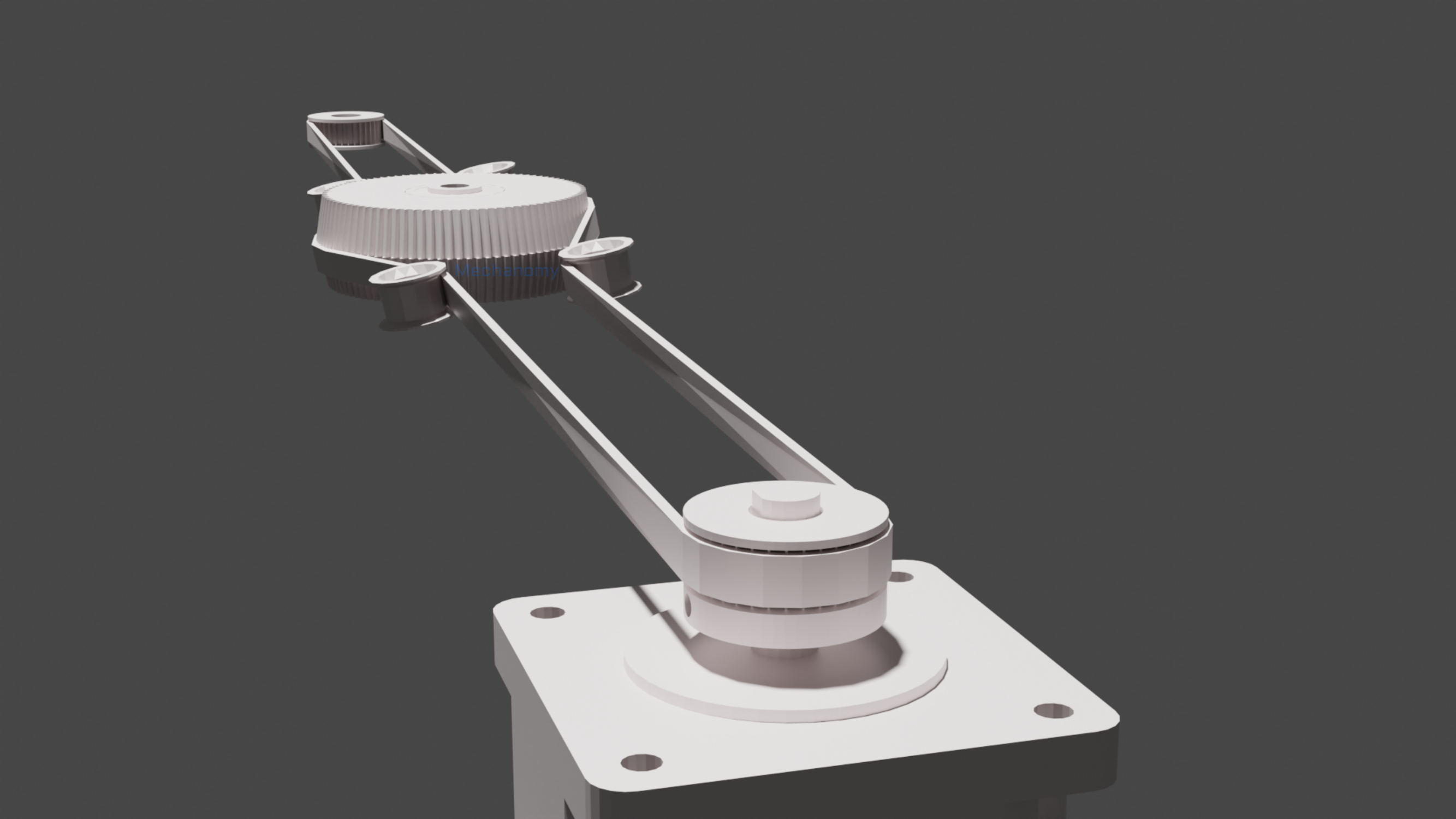
One result is the ConicalTwisted variant, in which the carriage idlers give the belt an axial twist over the free span while orienting it to engage conical coupled pulleys on the carriage.
CylindricalTwisted variant
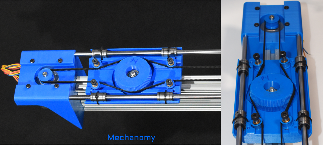
After the immediate performance of any variant, belt life is a major concern, and one that is challenging to answer analytically. The preceding variants take different liberties with the belt routing, but once taken seek to otherwise minimize the strain with an eye to the belt life. The CylindricalTwisted variant pushes way beyond these concerns to maximize belt engagement in a compact transmission.
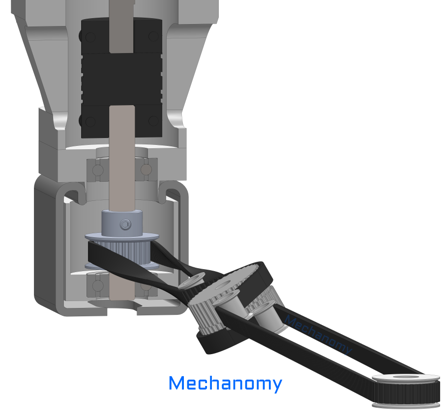
Several features are apparent:
- the carriage idlers and coupled pulleys all share the same angle, 30° from horizontal
- the belt engages the drive pulley normally
- the free spans between the drive and carriage experience twists of 180° ± 30°
- this twist orients the belt teeth outward to increase the angle of wrap on the coupled pulleys, as was done in the CylindricalDeflectingDual above
- after the carriage pulleys, the belt remains teeth-out around the return pulley
This variant is most similar to the ConicalAngled variant, but by twisting the belt over the free spans, the conical pulleys can be avoided in favor of cylindrical coupled pulleys.
The strut design constraint and objective to maximize the transmission ratio drove the choice of the 30° angle of the coupled pulleys, leading to a ratio of -0.024 and angles of wrap of 85° and 121° on the smaller and larger coupled pulleys. This creates a capable and cost-efficient linear slide:
Of course, use of a double-sided belt removes the major limitation of this variant, the 180° twist between the motor and carriage; without this, the 30° twist to/from the carriage is tolerable in many applications.
Looking Forward
We hope you enjoyed this brief presentation of the Moover variants. The concepts described here are the fruit of a particular approach to systems design, one that has become possible only recently and yet we believe will be necessary to create the systems of tomorrow and manage their complexity. Mechanomy is building software tools and workflows that support this, but we need the help of engineers to refine these ideas and bring them to the market. Much more could be said about the properties of each Moover variant, some of which may be included in a whole-system optimization and others which require experimental determination.
As this project was primarily a design exercise, none of the variants can be said to be fit for a particular application, but rather they may be taken as initial outlines to base subsequent development. That development might be organized along two directions. The first is determining key properties of the chosen belt-pulley system. That is, the performance and life of candidate belts under the considered belt routing, and the pulley design and operational limits of the necessary belt-pulley engagement. The second direction is designing one of the variants for a specific application or market segment incorporating the prior learnings.
The major question not addressed here is whether there is an opportunity for differential belt transmissions in the linear actuator market. While a suitably-designed differential belt linear stage may compare favorably to particular traditional screw, belt, or rack and pinion stages, developers should not constrain their efforts to existing markets but examine whether the variants permit expansion into new market niches. The differential belt transmission may be particularly appropriate for long-travel, lower resolution, lower design life, and lower cost linear stages.
In many ways the Moover project was the inverse of a typical development, starting from the observation of a mechanism that is not present on the market and asking why it is missing. This freedom from hard requirements made it an enjoyable project, but as an engineer it is a bit dissatisfying to be unable to answer market questions analytically. If you happen to be looking for a low-duty, cost-efficient linear actuator we would love to hear about your application and why existing technologies are insufficient.
