
Differential Belt Transmission
Monthly MechanismDifferential BeltThe differential screw and differential winch Monthly Mechanisms are relatively well and widely known but this month's mechanism is rarely seen: let's look at the differential belt transmission.
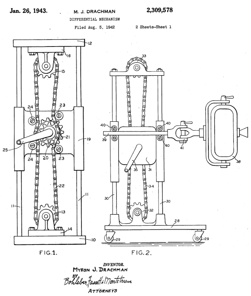
Myron Drachman's 1943 patent appears to be the first description of the idea, wherein a closed chain engages two coupled sprockets on a carriage moving between two fixed, freely-rotating sprockets. The coupled sprockets differ in their number of teeth, and hence radii, such that their rotation causes the carriage to move.
As depicted, the larger sprocket has 15 teeth and the smaller 10, leading to a transmission ratio of 0.2. With this ratio, rotating the handle clockwise one revolution would lower the imager a distance equivalent to the radius of the smaller sprocket. In contrast, if the chain were fixed and engaged only with the larger sprocket, the carriage would move 3/5ths the distance between the upper and lower sprockets. Using a differential chain mechanism increases the vertical position resolution of the imager while decreasing the force required move it.
Analysis
To see this calculation, let's simplify the system to the two fixed, freely-rotating pulleys, and the two coupled pulleys of differing radii. The coupled pulleys and any necessary idlers are free to translate between the fixed pulleys, and all pulleys engage the same closed belt without slip.
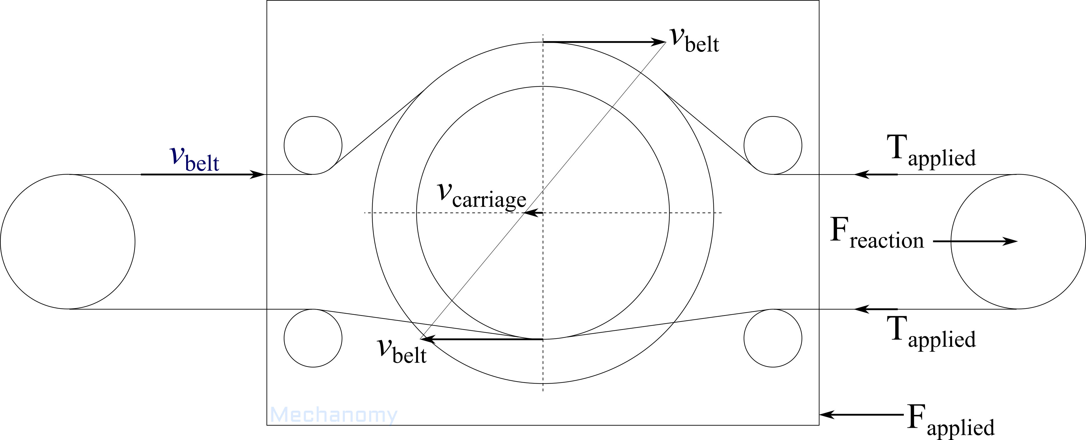
The transmission ratio can be derived and visualized via the method of instantaneous centers: If we apply a translational belt velocity to all pulleys and assume no belt slippage, the belt will make the larger pulley rotate with a velocity of and the smaller . As these rotational velocities differ, for the larger and smaller pulleys to remain coupled the carriage must move in the direction and speed indicated by , or the belt must stop moving, break, or slip on one of the pulleys. This is depicted graphically by connecting the tips of the velocity vectors of the coupled pulleys and drawing a vector from the pulleys' center of rotation horizontally to the line.
From this, the transmission ratio is
which can be used to find the carriage velocity
and position
The leading negative sign in the transmission ratio indicates that the carriage moves oppositely to the belt segment engaged with the larger pulley.
Like the differential screw and winch, the transmission ratio goes to zero as the coupled pulley radii approach equality, but unlike those mechanism the closed belt or chain can be circulated infinitely many times, allowing very large ratios to be realized without limiting travel.
As with any belt, chain, or cable system, engagement of the belt with the pulleys is essential to the performance of the mechanism, as any slippage between the belt and pulleys shows up as unwanted carriage movement or lack of movement. As drawn, any loads on the carriage are borne by two segments of the belt to one of the rotatably fixed pulleys. The benefit is that is divided between the two segments, allowing larger loads to be moved or doubling the carriage stiffness relative to a typical belt linear actuator.
In Use
Aside from a few citing patents, the differential belt mechanism does not appear to be used commercially in any machine. Why is this? Have you seen one in use? I'd really appreciate if you shared any sightings, take a picture and tag @mechanomy_ or send it our way.
The primary limitation appears to arise from the coupled pulleys, that a belt or chain engaging these must translate out of the plane defined by the fixed pulleys. In Drachman, above, the chain needs to translate towards the viewer to engage the smaller coupled sprocket and then translate away to meet the larger sprocket. While chains and belts are not designed for this binormal (perpendicular to the 2D plane of motion) bending and translation, round belts and cables are certainly capable of bending on arbitrary axes and would seem applicable to this mechanism.
Moreover, mechanism design is the process of understanding and making tradeoffs. The question isn't whether a belt or cable is designed for binormal bending but how the performance of the mechanism changes from this atypical operation; is the belt or chain's life reduced by 2 or 30% for a given system design? Later this month I'll introduce our Moover linear stage project which raises many design questions and sketches some answers, please stay tuned.
As always, comment on Twitter or LinkedIn, and subscribe to see next month's mechanism.
— Ben Conrad
- Next: New Work-in-Process Packages
- Previous: Differential Winch