
The Tensegrity Table
Tensegrity TableMonthly MechanismFor July's #MonthlyMechanism, we're modeling a tensegrity table in Modelica:
The tensegrity mechanism
'Tensegrity' is bit of a portmanteau implying the significant or novel use of tensile elements in some structure, they being essential to its structural integrity. I'd recommend clicking through to the tweet to see how placing a soda can on the top causes the structure to move.
Before jumping into Modelica, let's talk through what's going on in the above figure. Three ball-chains connect the corners of the triangular platforms, and in the center are two opposing arms joined by a fourth chain. The weight of the upper platform is borne by the two arms and connecting chain, with the outer chains keeping the platforms aligned through their tension.
If the tension in the center chain is increased, that increase is evenly divided between the outer chains. Similarly, increasing the tension in any of the outer chains will load the arms and center chain, and it will slightly affect the alignment of the platforms. As the loading on the top platform increases, so too does the tension in the center chain, and as long as the load is placed centrally the table should be able to support it. Off-center or moving loads challenge the mechanism and can lead it to adopt an alternate, non-table-like configuration. Describing these load limits and the zone of stability for a given table design and loading are some of the questions that a dynamic system model should be able to answer.
Modelica model elements
We're going to use elements from the MultiBody Dynamics package of the Modelica Standard Library 4.0 and simulated by OpenModelica 1.19.2. The ball chains will be treated as springs, with initial lengths and spring constants eye-balled to approximate the stiffness of a small ball-chain. The platforms and arms will be taken as separate rigid bodies.
Note that, at least for now, the use of rigid, non-beam elements in the platforms and arms prevents considering their contribution to the system dynamics. Thinking about the apparent stiffness of the upper platform to loads placed on it, I wouldn't be surprised if the center chain is responsible for 70% of the platform compliance and the two arms for the remainder. But other configurations are quite possible, with greater arm deformation and a stout center chain or with an even weaker central link.
We'll take the overall table height to be 100mm, the radius of the tip chains from the center to be 50mm, and the thickness of the platforms and arms to be 5mm. The upper and lower platforms are modeled as solid discs and the arms as opposing L-shapes, such that the center chain is 30mm in length.
To exercise the model, I apply an increasing force to the center of the upper platform, directed downward, with sinusoidal horizontal components. Many other loadings can be considered with a little fiddling to ensure they're applied to the platform as intended, but this is sufficient for now.
Block diagram
Modelica models can often be expressed graphically, especially at the system level. The graphic isn't quite complete, as a couple parameters are defined only in-text, but see the attached model text if you want to explore and simulate it yourself.
Simulation results
Graphically, the loading is:
The table is initially unloaded, showing a jump to the initial solution and basic stability, followed by increasing motion and eventually a drastic reconfiguration.
The reconfiguration is quite telling, if you watch a couple times around t=38, the upper platform displays a significant rotational motion around the Y-axis, this is distinct from the circular translation from the XZ loading. This rotation grows until t=42, when the rotation of upper platform becomes too large for the outer springs to counteract, leading to the reconfiguration. (Note the video time is a little slower than the simulation time.)
Looking at the motion of the upper platform with time shows the jump to the initial solution and circular, horizontal motion, and then the reconfiguration to a lower-energy state at t=31.204s and vertical load of 338N (76lbs).
The load is applied at 5sec, with the vertical component loading the structure and the sinusoidal X and Z components inducing a circular translation in the platform (no torque is applied by the load). While the table hardly displaces vertically, the same load directed horizontally quickly leads to large motion, indicating that the table is susceptible to horizontal motions.
The springs show extension from the loading around their unstretched lengths...
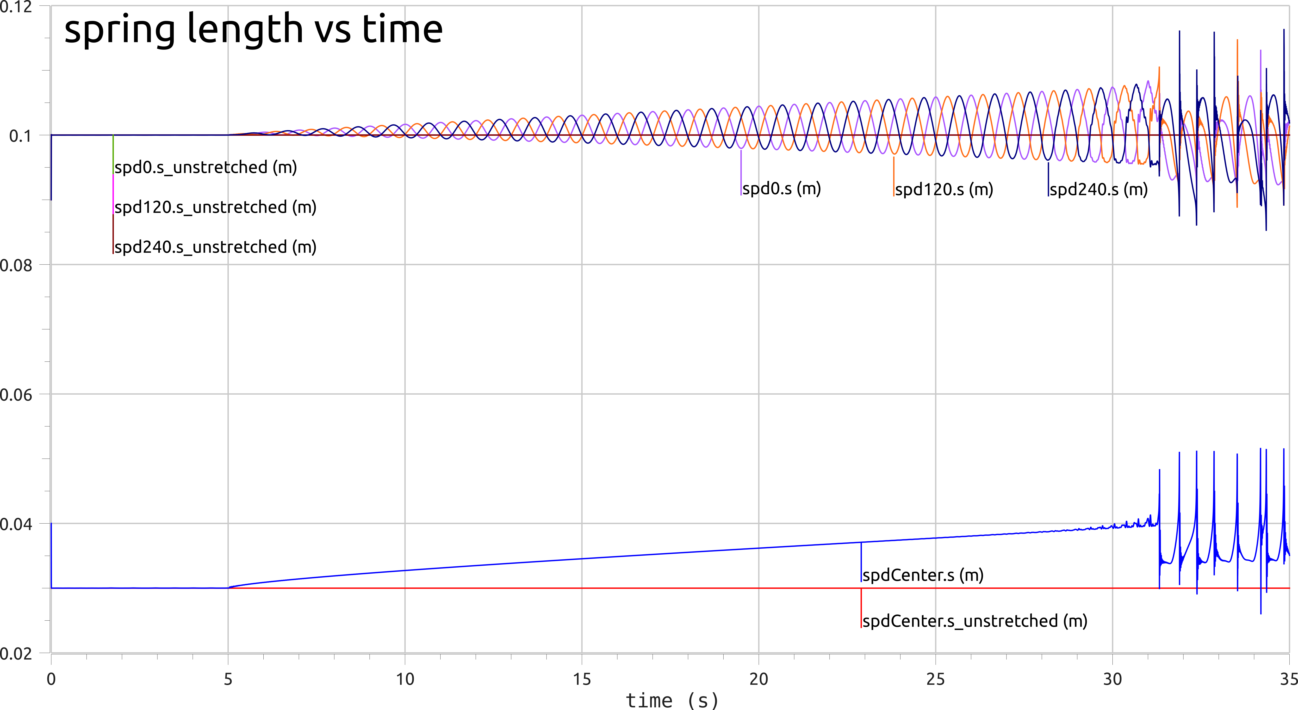
...which result in spring/damper forces:
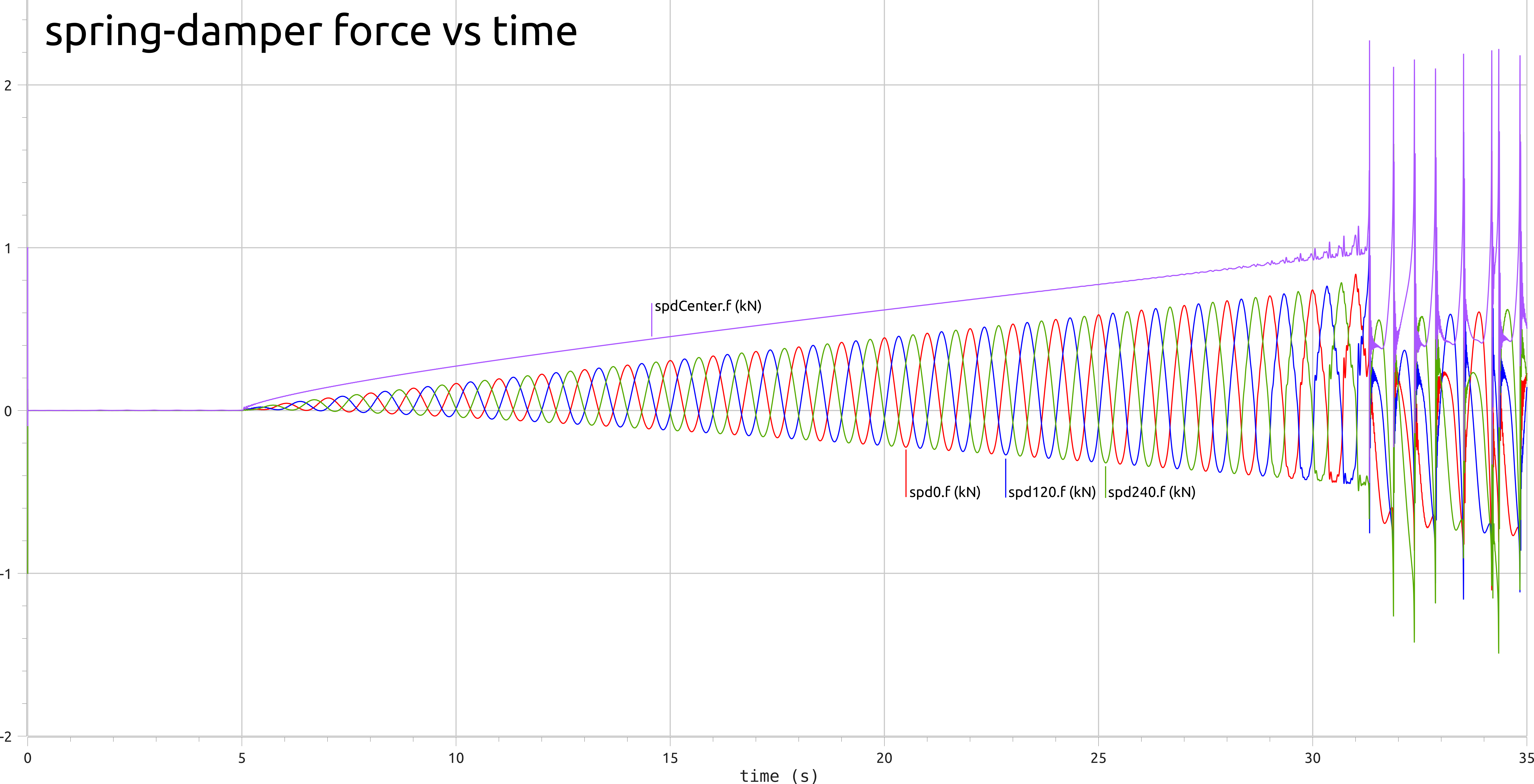
Note here a modeling error: the springs are exerting compressive (negative) forces while a correct model of the ball-chains would load them only in tension. If this were fixed the reconfiguration would likely occur earlier, as the table's rotation would not be resisted by the spring(s) in compression, nor would a spring resist the platform's eventual translation in its direction.
While we can see the moment of reconfiguration in all of these graphs, the design question is "how can I influence when failure occurs relative to the needs of my application?" This can be challenging to draw out though simple video or timeseries graph inspection.
A slight improvement is a spatial graph comparing simulations with different design parameters. In the next figure, the length of the center spring is varied by ±5mm, which has the effect of slightly changing how quickly the spring's force increases with the horizontal displacement.
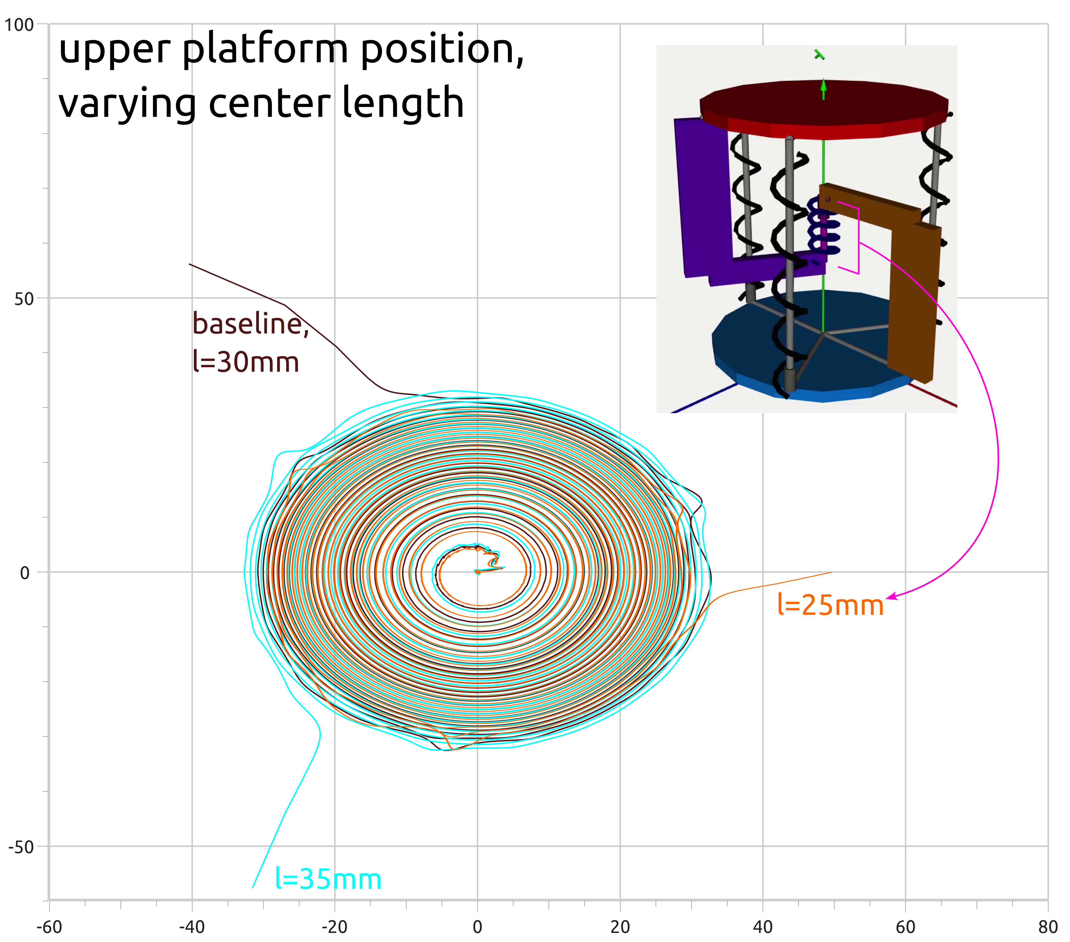
Increasing the center distance reduces the horizontal stiffness, leading the 35mm to depart at a lower load than the 30 and 25mm spacings. This is also shown in the larger diameter trajectory of the larger center spacing, with the 35mm completing 26 revolutions to the 30 and 25's 27 revolutions.
Summing up
The above graphs agree with and bolster first-hand experience with this mechanism, but the larger value of system modeling is to have a ready-resource for what-if analyses, to have something at-hand that allows ideas to be quickly specified and tested to, at least, a first degree. For many systems, a simulation can be run faster than prototypes created or experiments conducted, augmenting a designer's intuition while encouraging better communication and system documentation.
While this system is simple enough that it could have been derived by hand, which would grant access to the algebraic equation of motion and enable classical dynamics, vibrations, and control analyses, physics-based modeling in Modelica extends to very large systems with thousands of degrees of freedom in a way that hand-derivation does not. Modeling physical systems involves many choices and approximations, understanding these and verifying their consequences are the kinds of tedious tasks that prevent more systems from being modeled. We're working on some solutions here, say hi or subscribe to keep in touch. And please share and comment on Twitter or LinkedIn as you prefer.
— Ben Conrad
- Next: Moover Linear Stage Variations
- Previous: New Work-in-Process Packages