
Sketching Involutes
Monthly MechanismSketchingInvoluteGearsGears are foundational to many mechanisms, and it is the involute curve that is responsible for many of their capabilities. In this MonthlyMechanism we're calculating and sketching the involute curve.
Many references describe involute curves by analogy to a taut string unwrapping from a cylinder, and some depict a mechanical curve generator. But these physical approaches do not translate into CAD, often forcing designers to find a commercial gear for basic design work. This post derives the involute function from a circle, explains the geometry, presents a function to calculate a gear tooth involute, and compares this to a commercially-available gear.
Deriving the involute of a circle
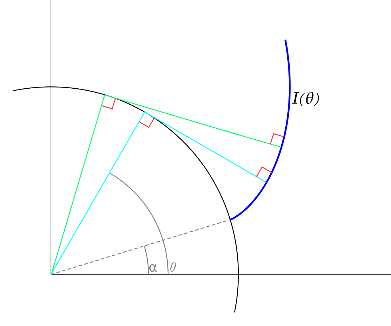
Involutes are typically described as the points that a string traces when it is unwrapped from a circle or other curve. More useful is the property that every point on the involute is tangent to the involute and tangent to some ray of the generating circle. This can be seen graphically as:
Involutes are expressed mathematically as
with being a curve parameterized by . In spur gearing the curve is a circle and .
Taking the derivative of with respect to gives
.
The magnitude of simplifies to .
Putting those into the expression of the involute, integrating from to , and simplifying gives an equation for the involute of a circle in [x, y]:
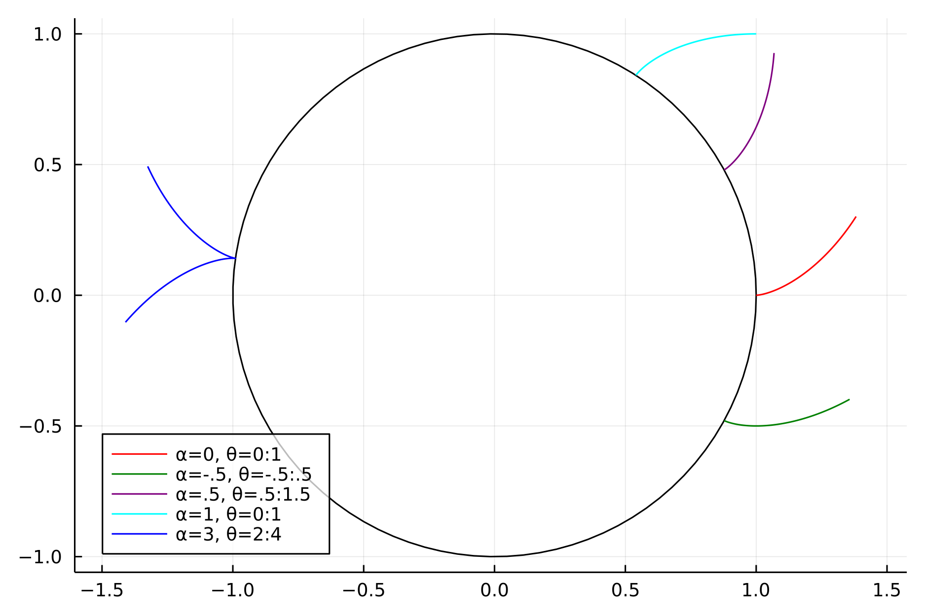
Plotting this while varying traces the involute, while changing moves the root of the involute.
Sketching
While the equation for an involute is essential, we need some geometry to apply it to gear teeth. Gear teeth are symmetric, often described as having a width and height, and arranged at regular angles.
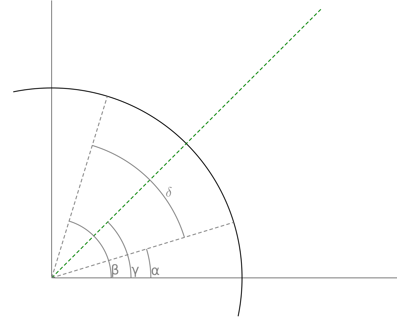
Let define the angle of the symmetric axis and thereby the overall angular location of the tooth about the gear, the angular width, and the radius of the circle at the involute's base. With these, the root angles of the two involutes that form the gear tooth are and :
The tooth will be formed from two involutes, one for each flank, and so we need to calculate the starting and stopping angles for each involute equation. The starting angles are and , but the stopping angles depend on the tooth height, as measured along the symmetry axis. Calculating a that leads to a particular tooth height requires a bit of geometry, here's the basic setup:
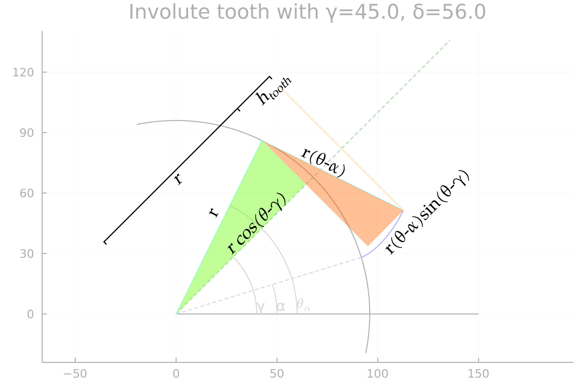
The result is
for the flank rooted at or
for the other flank. To actually find from these, use a 1-dimensional solver (find_zero, fzero) with an objective function comparing the desired tooth height and that resulting from a particular guess.
At this point, we have giving the x,y equations for the involute as a function of and , the starting angle as a function of and , and a 1d optimization to find the stopping angle .
Into CAD
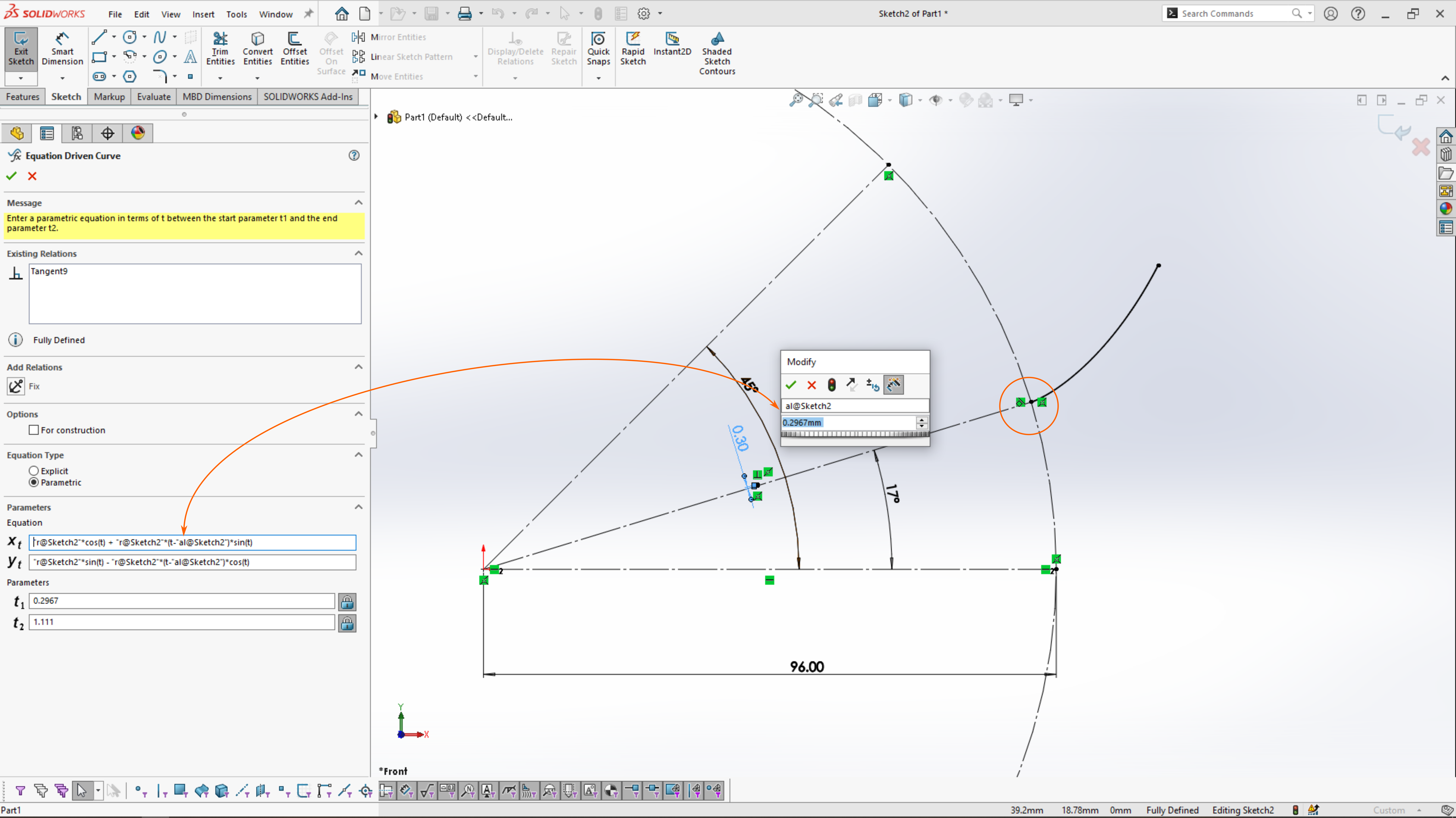
The last step is to express these in a form that CAD can accept. CAD packages vary greatly in how they implement particular features, here I'll use Solidworks 2022.
Our target is the equation-driven curve feature, which accepts curves in , parameterized by a variable ranging from to . This function has a major limitation in not being able to use file properties, instead these need to be attached to geometry within the sketch and then referenced through the dimension name ("al@Sketch1"). Angles are given in radians for and , and you can see that I specified in radians as a linear dimension to avoid a unit error. Also, despite exactly specifying x,y, the equation curve is interpreted relative to one of the curve endpoints and not relative to the sketch origin.
With those caveats, we have the ability to enter the involute into Solidworks and generate a 3D gear tooth.
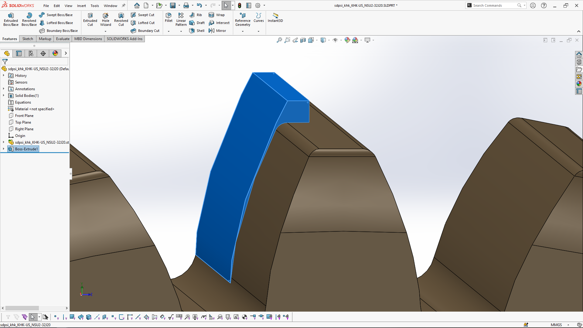
The preceding figures of involutes were exaggerated to better show any geometry or plotting errors; more reasonable is a 32 tooth module 2 gear like this one from SDP-SI. For a metric gear described by module, number of teeth, and pressure angle, we can calculate the equation curve in Julia by:
using Roots
function calcThetaHeight(; r, gm, al, ht)
  htal(th) = r * ( cos(th-gm) + (th-al)*sin(th-gm) - 1 )
  fal(th) = ht - htal(th) #the objective function
  return find_zero(fal, gm + (gm-al)*2)
end

function printEquationCurve( gearModule, nTeeth, gamma=π/2, pressureAngle=deg2rad(20) )
  addendum = gearModule
  dedendum = 1.25*gearModule
  pitchD = gearModule * nTeeth
  r = (pitchD - 2*dedendum)/2

  toothThick = gearModule * pi/2

  delta = 2*asin( toothThick / 2/r)
  alpha = gamma - delta/2

  toothHeight = addendum + dedendum
  # p = InvoluteTooth.plotTooth( r=r, gm=gamma, dl=delta, ht=toothHeight )
  # display(p)

  thal = calcThetaHeight(r=r, gm=gamma, al=alpha, ht=toothHeight) #the find_zero function

  println("Equation Curve with r=$r and δ=$delta for a $nTeeth module $gearModule gear: ")
  println("xt = $r*cos(t) + $r*(t-$alpha)*sin(t)")
  println("yt = $r*sin(t) - $r*(t-$alpha)*cos(t)")
  println("t1 = $alpha")
  println("t2 = $thal")
end
Equation Curve with r=29.5 and δ=0.1065 for a 32 module 2 gear:
xt = 29.5 * cos(t) + 29.5 * (t-1.5175) * sin(t)
yt = 29.5 * sin(t) - 29.5 * (t-1.5175) * cos(t)
t1 = 1.5175
t2 = 2.0905
Excepting Solidworks' curve approximations, the resulting half-tooth, blue, is close to the manufacturer's model through the flank. They appear to use a smaller tooth height than calculated by the standard, but gearing is full of optimizations. The many textbook-quality descriptions of gearing are enough to produce a basic gear, but greater accuracy requires consulting industry standards. While the comparison to the manufacturer's model is favorable, the model should only be treated as an approximate representation of the real part.
Wrapping up
Despite the many references that discuss gearing, all that I have seen gloss over the drawing of the tooth involutes by computer or in CAD. This presentation was brief but linked the basic equation of an involute to its use in generating gear teeth. The plots here were generated by my InvoluteTooth module and plotted via Plots.jl. Real gears have many additional features that were not modeled here, but I hope this post provides a quick starting point to drawing involute gears. If this left you wanting a more thorough treatment, reach out so that I know what to expand.
As always, comment on Twitter or LinkedIn, and subscribe to see next month's mechanism.
— Ben Conrad