
The value of intermediate sketching
SketchingCADsystem developmentWhat tools do engineers have to explore new ideas?
That is, once you have an idea in your head, what tools do you use to evaluate it? Most hardware engineers turn to sketching and CAD. Sketching (on paper, whiteboards, in CAD) fixes basic concepts and relationships, allowing engineers to focus on particular details, often those required to create a conceptual CAD model. However created, the first conceptual CAD model often becomes the basis for subsequent work, appearing more professional than hand sketches while better communicating the idea to diverse teams. This leads to a problem in that the CAD model has fixed a variety details that have not actually been decided by the development process; while the key ideas are in the originating sketches, at this early stage everything beyond these in the model is mere consequence.
Mechanomy believes that if engineers had additional and better tools for intermediate system sketching and analysis, developments would proceed more quickly while also generating artifacts (plots, models, etc) that contain only the key information that has actually been considered by the development team.
As needed by Moover
The Moover project is an example: at the core of each variant is a fundamental design sketch which contains the central design trade. These master sketches were drawn in CAD only because of the lack of other tools (our Geometry2D and BeltTransmission are first steps towards remedying this particular case). Moover was chosen for development because of this simplicity. Not many systems are reducible to a single sketch, but it can be said that a major objective of development is to identify the design kernel and understand its properties.
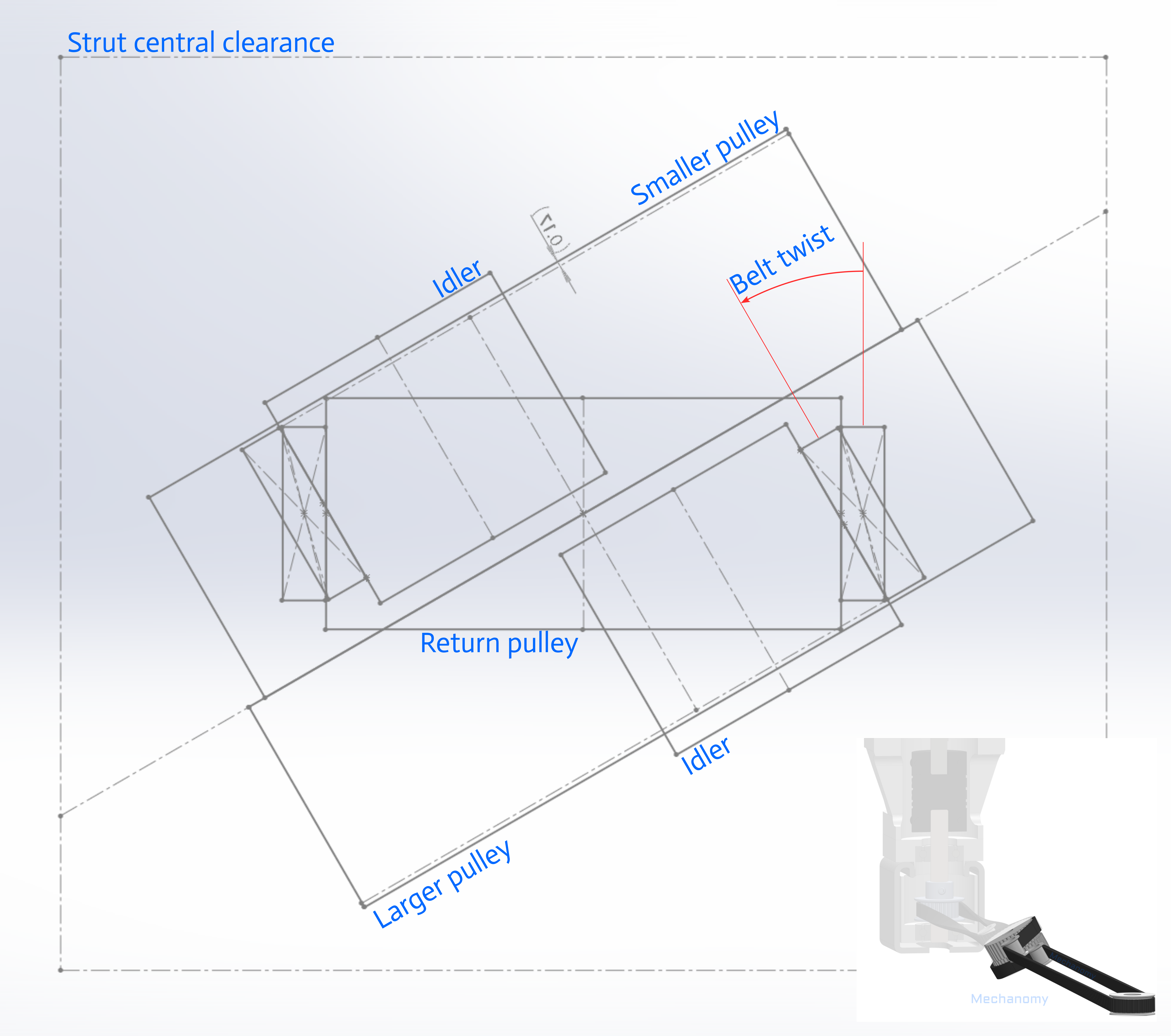
The sketch above is the kernel of the CylindricalTwisting variant, it contains the essential geometric relationships that communicate the belt between the horizontally-oriented drive and return pulleys, and the inclined coupled pulleys and idlers. Transmission performance, belt engagement, pulley sizing, belt life, all are implicit in this sketch...but the CAD sketcher lacks any ability to provide data to subsequent analyses, instead every iteration must be manually checked for consistency and the results hand-copied into downstream processes.
New tools are needed
Stepping back, the virtue of sketching concepts is the ability to fix certain elements to communicate them to team members and free your mind to consider other aspects of the system. Hand-sketching is quick but hard to change, often serving as a canvas for imagining functions that are too challenging or tedious to draw out. Just as sketching a belt system by hand is made easier and clearer if you have a compass, libraries like BeltTransmission can enable the quick expression of new ideas, if they are available and known.
We're working on more tools that assist the early exploration of system designs, say hi if you'd like to hear more. While a CAD-like sketcher is not on our plan right now, I'd love to hear of any interest or motivating applications. As always, please share and comment on Twitter or LinkedIn, and subscribe to future articles.
— Ben Conrad
- Next: Announcing Composer
- Previous: Sketching Involutes