
Renishaw Equator
Monthly Mechanismdelta mechanismOne of the joys of attending trade shows is seeing machines in-person; at IMTS last month I spent a bit of time looking at the mechanical design of Renishaw's Equator gauging machine and want to share some observations for this MonthlyMechanism. As I have some experience in delta robot design, here are some highlights and conjectures on the design of the Renishaw Equator 300.
The Equator is a delta robot for automated gauging of machined parts. Gauging is the measuring and comparing of a part against a known or desired baseline, and the Equator is designed for rapid gauging of parts in order to quickly discover any deviations and institute process changes. In their press videos, Renishaw shows an Equator stationed next to a machining center to gauge a freshly-machined part. If the gauging discovers tool wear, a wear offset can be sent to the machine to correct the next part.
The basic task of the delta robot in the Equator is to move the probe around critical features of the part while measuring the deflection of the probe. Since any deviations between the commanded movement and the probe measurement will be attributed to machining errors on the part, the robot needs to be extremely precise while moving over a large volume. The designers, then, likely had design goals on probing accuracy and probing speed.
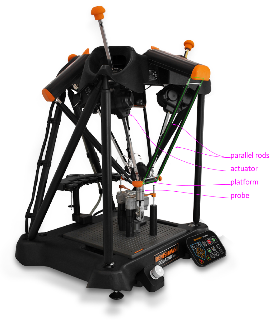
To achieve this, a delta mechanism is used. Delta machines are designed to guide a platform in pure 3D translation within some volume. Notice in the prior figure the light green polygon, which, in the absence of camera perspective distortion, would be a parallelogram, having two pairs of parallel sides. As the platform moves the angle of the parallelogram will change, but the stiffness of the four links ensures that a single angle can describe the entire linkage. When three of these parallelograms are placed around the moving platform, each parallelogram controls a degree of freedom. Before assembly the mobile platform has 3 translational and 3 rotational degrees of freedom; adding the parallelogram linkages remove these three rotational degrees while permitting the translational degrees.
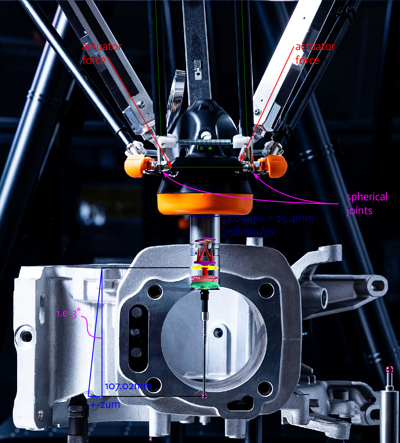
Looking more closely at the moving platform, the construction of the spherical joints can be seen to be a cup element on the rod end which caps a spherical standoff on the platform. It should be clear that the rotation between the rod cup and spherical standoff is limited by when the cup runs into the edge of the standoff. The spring controls a rod's rotation about its axis, thereby keeping the rod cups approximately centered on their spherical standoffs. It also likely permits the spherical standoffs to escape the rod cups if the platform or probe runs into an unexpected obstacle or if either are bumped during part placement, possibly avoiding machine damage.
During operation, the brochure lists the 'comparison uncertainty' as ±2μm. I haven't found the definition of this term — I don't believe that it is the absolute positioning accuracy of the probe tip — but even if this is just the open-loop repeatability of the probe location to a prior run, that is an excellent achievement to holds over the entire workspace. If we take it as the feature size that can be detected by the Equator with a suitable scanning probe, we might infer the blue triangle drawn in the figure. In order to be able to detect ±2μm translational movement at the probe tip, the angular deviation of the platform must be significantly less than 1e-3° while moving. That is, its movement is rock solid under the small probe contact loads and repeatable after gross translations while under large acceleration forces. I'd really like to see a technical presentation on the mechanism dynamics.
In normal operation the robot moves the probe about the part's critical features, comparing the deflection of the present part against the reference. This movement is driven by three actuators which are positioned between the parallelograms. This is the most striking design decision because it increases the part count and, at first glance, does not clearly improve the machine's performance. With a little time I've thought of a couple of possible benefits, but it is hard to gauge how much of an improvement any of these may make.
First, actuator forces are applied inside the spherical standoffs of the parallelogram linkages. Directed this way, the actuators have a smaller moment arm by which they may induce platform rotation, thereby permitting greater accelerations. Additionally, with the actuators split from the parallelograms, their forces are inherently shared between parallelograms, improving platform stability.
Second, while introducing additional mechanism complexity, separating actuation from guidance may permit larger spherical joints to be used on the platform and base than if their operations were combined, again improving stiffness and permitting greater speed.
A third benefit to this separation may be that it enables the use of linear actuators which give more uniform movement and better position sensing than traditional architectures. The actuators feature a motor and transmission driving a U-shaped bar through what may be an Omega belt drive. Though difficult to see, the bar holds a Renishaw linear encoder strip to provide position feedback of the bar's position. The actuator housing is gimbaled to rotate about a single point on the base, and the connection to the moving platform likewise has a spherical connection (approximated by two intersecting revolute joints). This second significant design decision to use gimbaled, linear actuators was likely made in order to have better encoder accuracy over the workspace, as rotational encoders on rotating arms can have a double sine loss in accuracy over the workspace. This approach does require some clearance above the machine, as the the orange safety bumpers on the ends of the actuator bars move about, but that likely isn't a large concern when placed next to a machining center.
I'm still puzzling over one last feature which I haven't found a good video or diagram to illustrate, which is the rotation of the orange-capped upper arms to which the delta parallelograms attach. In the first figure, it is not the camera's perspective but the left shoulder/arm is actually at a steeper angle than the front. Now, as long as the parallelograms stay the same length and the shoulder blade movement plane is perpendicular to the original base plane, the mobile platform will continue to move without rotation. But shoulder blade movement shifts the delta robot workspace, increasing the total volume. I suspect that the shoulder blades are unactuated but spring assisted, so that when the commanded position is within the delta's workspace, only the parallelograms move, but on reaching the edge one or more of the shoulder blades will deflect to permit extra workspace. If it can be assumed that the delta linkages are at the edge of their workspace, then the same linear actuator encoders should also be able to calculate the shoulder blade deflection. That said, nothing about this design suggests sensitivity to cost and the shoulder blades may be individually actuated and measured.
Renishaw made a number of significant design decisions in their Equator 300 and 500, all of which are outside of typical delta robot designs. I've tried to collect a couple of reasons for these, but it would be great to have a Renishaw engineer explain their design goals and particular solutions. Moreover, the complexity and interrelated-ness of delta robots make them a really interesting system for design optimization, one we may return to in the future. Until then, I look forward to any comment on Twitter or LinkedIn, and be sure to subscribe to see next month's mechanism.
Both figures modified from these originals.
— Ben Conrad
- Next: Compression Springs
- Previous: Announcing Composer