
Modeling Fireball's Vise Hammer
Monthly MechanismJason at Fireball Tool is a fabricator and a demanding tool user/builder; he's previously tested the failure modes of shop vises, which left him wanting a better shop vise, resulting in the HardTail vise. To show its capability, in this video he builds a vise torture test rig around a swinging hammer.
For this MonthlyMechanism I'll model the Vise Hammer in Modelica to estimate the impact energy applied to the tested vise.
Modeling
The Vise Hammer is inspired by his manual testing of shop vises, where he quickly tired from swinging 4 and 5 pound hammers, making his testing less consistent than desired. This experience gave him a starting point and a basic design objective of approximating a hammer swing while increasing the impact. For the hammer head, he found an old, 53lbf rock drill bit which he mounted on a 3ft arm swinging in a vertical plane. The basic design is then to raise the hammer head up and let its gravitational potential energy propel it into the vise under test.
While the shaft and pivot arms are readily approximated with simple shapes, I drew a quick, approximate model of the hammer head, shaft, and pivot arms in CAD by eyeing the dimensions and checking them against the approximate weights he gives. Of course, if you had access to the system you could take more detailed measurements but these will get us rolling.
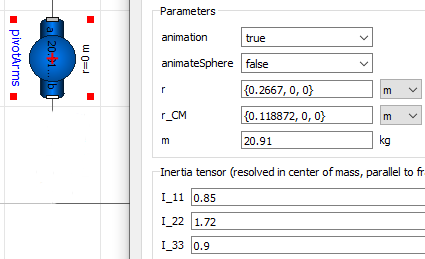
The core of the model is the Modelica.Mechanics.Multibody.Parts.BodyShape, which allows arbitrary rigid bodies to be modeled from their moments of inertia. Vector locates frame_b with respect to frame_a and similarly locates the center of mass with respect to frame_a. The inertia matrix is taken in frame_a for consistency.
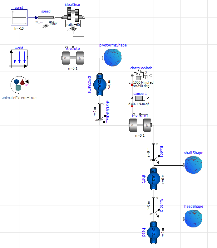
Two revolute joints provide the driven and free rotations, one between the fixed world and pivot arms, and the second between the pivot arms and the hammer shaft. In order for the bodies to connect correctly to each other, I use explicit frame transformations instead of modifying their internal vectors. I added some light damping to the shaft's revolute joint to approximate the plain bearing he used.
One sore point of Modelica, and most physical modeling engines, is the challenge and computational cost of modeling contact. To raise the hammer the motor rotates the pivot arms until the hammer shaft contacts the second shaft on the pivot arms, preventing further rotation. I approximated this contact with a large backlash via the rotational ElastoBacklash2 element. In this, I defined a 20° sector where the shaft is in 'contact' with the second bar, leaving 340° of free rotation in the 'backlash' sector. The main implication of this is that the edges of 'contact' zone are softer than they are in the real system; I used a spring stiffness of 1e3N-m/rad and damping of 1e3N-m-s/rad.
This also means that I am not attempting to model the vise or the impact of the hammer on the vise, which prevents estimating the 'break' force of a particular vise. Calculating this maximal force is tricky because it requires some idea of the stiffness of the vise to understand how it will absorb the hammer's energy. While the hammer mechanism is pretty simple, the amount of contact between the various parts of the vise make it much more challenging to model off of eyeball measurements from a video.
Returning to the vise hammer, driving the pivot arms is a rotational speed source and an ideal gear with a 60:1 ratio. Neither of these matter, as their dynamics do not meaningfully affect the hammer's impact energy.
The resulting block diagram is pretty simple, with the fixed support located upper left and the hammer head lower right. BodyShape should be able to accept CAD files for animation of the CAD parts, but it or OpenModelica is having some unspecified error on *.dxf or *.stl files that I was not able to work around. Instead I used DLR's Visualization Library to render the CAD shapes in the (disappointingly poor) animation.
Results
The first result is the animation, which communicates the idea of the mechanism and suggests a couple areas for greater focus.
We clearly see the hammer rising under the rotational speed source and falling with gravity.
The next graph shows the rotation of the hammer shaft (revolute1.angle, red), kinetic energy of the hammer head and shaft (keImpact, blue), and the torque provided by the rotational speed source (revolute.tau, green).

We see that at impact the energy of the hammer head and shaft is 485J. As noted above how the vise absorbs the energy is the key to passing Jason's test. If the point of impact on the vise deflects by 1mm, the vise needs to withstand and that sounds expensive. Adding compliance to the vise so that it deflects by 1cm similarly reduces the force to a more manageable . Beyond these basic estimates, a FEA simulation of the vise body and part being struck by the 485J would more clearly show how the energy travels through the vise.
Returning to the graph, I'll close by pointing out the severity of the post-impact collisions between the hammer shaft and pivot arms, visible in the revolute.tau torque curve. Though reduced by the chain transmission from 1946Nm to 32Nm, the gears in the gearmotor may still be seeing a torque 6x larger than required to raise the hammer. If allowed to continue this would lead to failure in the gear teeth.
Files
I wrote this model in OpenModelica using the DLR Visualization Library. You can download the model file and CAD parts from Github.
Wrapping up
I love ad-hoc engineering and building, and it's pretty clear that Jason does too. It's fun to go straight from idea to prototype, but metal fabrication takes space, tools, and material, making it less accessible. It's also clear that today's software prototyping tools are not as capable, fast, or satisfying to use as those in physical prototyping; my hope is that we will soon get to a place where they are that capable. If you want to follow Mechanomy's efforts towards this, please subscribe to see next month's post and share and comment on Twitter or LinkedIn. And if you want to help, please say hi.
— Ben Conrad
- Next: Automate 2023
- Previous: RapidSlide Adjustable Wrench